Radio Direction Finder
This equipment is a direction finder for marine use.
In short, it is a AM radio having a rotatable bar antenna.
For Japanese radio kids in mid to late 1970s, you guess this is a grandpa of
Panasonic Cougar series portable
radios.
|
|
An bar antenna of AM radio has a directional characteristic, like an "8" letter shape.
When the antenna bar points to the transmission antenna, the sensitivity becomes minimum.
So, if you have a knowledge where the transmission antenna is located,
you can tell the direction (or 180 degree opposite) to the antenna from where you are.
If you receive another radio station in a different city, then you can draw two lines on your map.
The crossing point indicates the location where you are now.
Such an idea itself is quite old; Hallicrafters sold a model S-30 back in 1940,
which was designed solely to this purpose.
Japanese radio kids in 70s should immediately remind the "Gyro Antenna" equipped in the Panasonic Cougar series.
The Cougar No.7 was my very first shortwave radio.
A huge map of Japanese islands, showing locations and frequencies of a thouthands of broadcast stations,
came with the radio.
I rotated the Gyro Antenna, draw lines on the map,
and I found that my house might be located somewhere on the border between Gunma and Saitama prefecture. ;-)
|
|
|
|
Position accuracy obtained by such a technique cannot be satisfactory enough, off course -
and supposedly, cannot be used in middle of the ocean.
However at that time, GPS was simply beyond of anyone's imagination and expensive Loran or Decca was out of consideration -
many yachts and pleasure or fishing boats would appreciate very much if they could tell which way to go home.
Nowadays a GPS receiver with less than 100 meter accuracy can be purchased in less than $100 -
no one would use an equipment like this anymore.
It is but still too new to be classified as an antique electronics.
No wonder the cheap selling price of this unit at the Foothill College flea market.
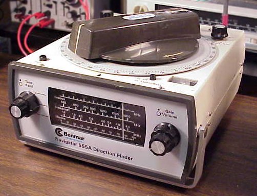
Benmar Navigator 555A Direction Finder
The nameplate of the product says "CETEC CORPORATION, SANTA ANA CALIFORNIA",
also an indication of "MADE IN JAPAN" can be seen.
I have no information which company actually manufactured the product, however,
a small logotype of "KODEN" is on the S meter is visible.
1979 sales catalog from Koden proved that this is a product of Koden.
Koden Corporation has a very long history in maritime electronics, well back before WWII.
Their produts such as radars, sonars, direction finders and GPS are highly admired among seamen.
I guess this direction finder was marketed under the name of the Bendix Marine.
The 555A sales catalog claims that the "Koden Direction Finders are used by yacht racers worldwide".
According to a Koden's anniversary company book,
an earlier version of direction finder similar to this model was used by a very famous maritime adventurer Mr. Ken-ichi Horie,
when he ventured to sail across the pacific, from Japan to San Francisco.
After a long voyage filled with many troubles and difficulties, he sailed under the Golden Gate Bridge and arrived his destination safely.
|
|
|
|
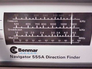
Unlike the Panasonic Cougar No.7, this radio is designed for a maritime use.
Its frequency coverage are, in addition to the regular AM broadcast band,
the longwave for beacon stations from 150 kHz to 420kHz, and medium shortwave)
from 1.6MHz to 4.6MHz for the maritime communication stations.
2 crystals may be used (optional) for fixed frequency reception in marine band.
It also has a BFO for morse code reception.
The BFO has a pitch control.
Furthermore it has a capability of receiving 160MHz FM band for the local weather stations.
To tune the weather station, dedicated tuning control (potentiometer type) is used.
|
|
|
|
|
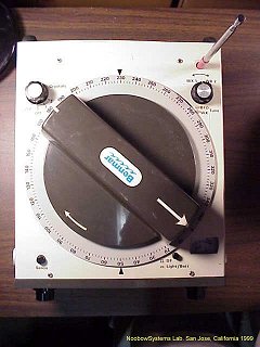
The bar antenna mounted on the top of the receiver
can be rotated 360 degrees freely
,
and its direction can be easily read with the accuracy of 1 degree by the rotatable ring scale.
By pressing a SENS switch, built-in rod antenna is connected internally to the AM reception circuit,
which allows quicker findings of the desired station.
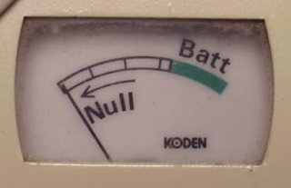
S meter is a must feature so that the null point (where the incoming signal becomes weakest) can be easily found.
Gain control helps to find the null point even if the signal is strong. KODEN logo is visible.
|
|
|
|
|
|
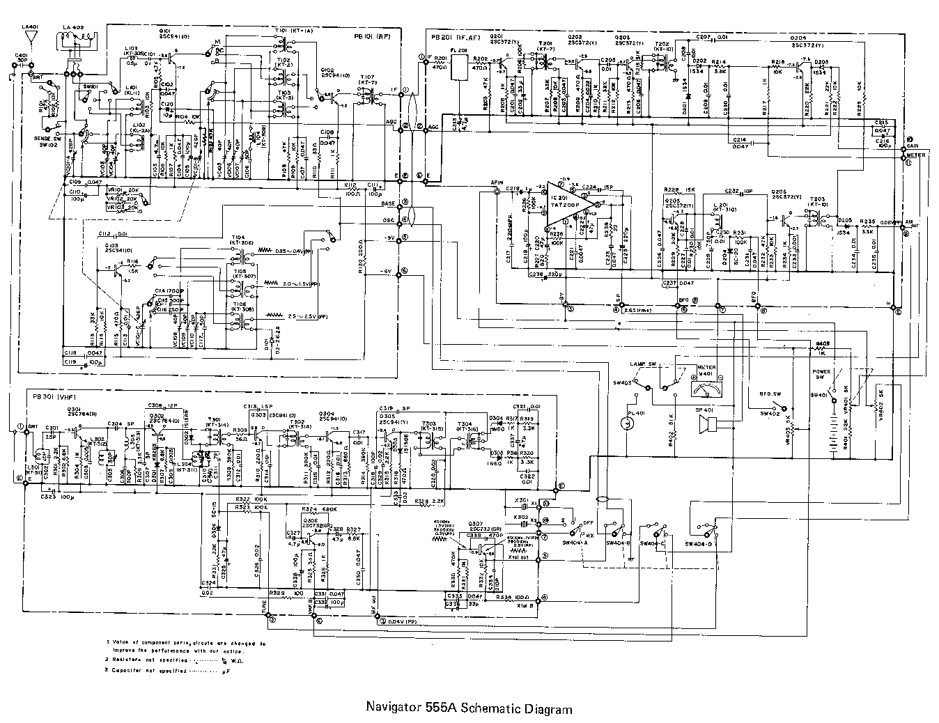
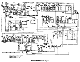
Rudy, another owner of NAV-555A, kindly sent this circuit diagram to me.
Total of 16 transistors are used in addition to 1 IC.
AM receiver circuit is a single superheterodyne, with 1 RF amplifier and 3 IF amplifier stages.
Intermediate frequency is 455kHz.
Sensitivity claims 30uV/m for the beacon band, 15uV/m for the broadcast band,
7uV/m for the marine band. Image rejection ratio claims 70dB for beacon,
50dB for broadcast, 40dB for marine band.
VHF-FM receiver circuit is also a single superheterodyne.
Tuning is done by altering local oscillator frequency by means of the varicap.
Interestingly, Japanese 555A sales catalog does not mention the VHF weather station reception feature.
Perhaps because there was no VHF weather stations in Japan.
The equipment runs from six "D" dry cell. It does not have an external power connector.
|
|
|
|
Designation
| Type
| Function
| Location
|
Q101
|
2SC941 (O)
|
AM RF Amplifier
|
PB101 (RF Board)
|
Q102
|
2SC941 (O)
|
AM Mixer
|
PB101 (RF Board)
|
Q103
|
2SC941 (O) |
AM Local Oscillator
|
PB101 (RF Board)
|
Q201
|
2SC372 (Y)
|
AM IF Amplifier (1)
|
PB201 (IF/AF Board)
|
Q202
|
2SC372 (Y)
|
AM IF Amplifier (2)
|
PB201 (IF/AF Board)
|
Q203
|
2SC372 (Y)
|
AM IF Amplifier (3)
|
PB201 (IF/AF Board)
|
Q204
|
2SC372 (Y) |
AM AGC Amplifier
|
PB201 (IF/AF Board)
|
D203
|
1S34
|
AM Detector
|
PB201 (IF/AF Board)
|
Q205
|
2SC372 (Y) |
BFO Oscillator
|
PB201 (IF/AF Board)
|
Q206
|
2SC372 (Y) |
BFO Buffer
|
PB201 (IF/AF Board)
|
IC201
|
TA7200P
|
Audio Power Amplifier
|
PB201 (IF/AF Board)
|
Q301
|
2SC784 (R)
|
VHF RF Amplifier
|
PB301 (VHF Board)
|
Q302
|
2SC784 (O)
|
VHF RF Converter
|
PB301 (VHF Board)
|
Q303
|
2SC941 (O)
|
VHF IF Amplifier (1)
|
PB301 (VHF Board)
|
Q304
|
2SC941 (O)
|
VHF IF Amplifier (2)
|
PB301 (VHF Board)
|
Q305
|
2SC941 (Y)
|
VHF IF Amplifier (3)
|
PB301 (VHF Board)
|
Q306
|
2SC732 (GR)
|
VHF AF Amplifier
|
PB301 (VHF Board)
|
Q307
|
2SC732 (GR)
|
VHF Crystal Oscillator
|
PB301 (VHF Board)
|
|
|
Fixing
The receiver package is not weather resistive; it could be corroded from the sea breeze.
However the particular unit I purchased looks pretty good cosmetically;
guessing the radio might have been used in a cabin, or was seldom used.
The rod antenna seems to have been replaced before, possibly taken from another junk radio.
A "Radio Shack" style general purpose battery holder was used in the battery compartment,
and it suffered from leakage.
So I replaced it with a new one.
The case was then opened, the interior as well as the dial scale was cleaned up thoroughly.
Bent dial pointer was corrected.
The receiver started its operation with fresh battery installed.
However it was soon found that the audio was somewhat intermittent.
Quick test revealed that the voice coil of the speaker, mounted on the bottom cover, was the problem.
Removed the original,
and placed an mini speaker with plastic duct enclosure which was also purchased at the Foothill flea market from Alltronics.
The easy fixing of the direction finder is now completed.
Use it
... as a radio receiver, not a direction finder :-)
What surprised me was its wonderful sensitivity.
The AM broadcast dial was filled with countless stations.
San Jose local stations were too strong that turning down the gain control was necessary to avoid overloading.
A community radio station in Fremont, approx. 30 miles away, was heard which was completely unable to find with ordinary home radio.
Selectivity is nothing noteworthy, and the tuning mechanism has a non negligible backlash.
Those prevent the radio from being a serious communication equipment, however,
it would be the best among the radio I own if I consider about enjoying the medium wave DXing.
Rotatable bar antenna greatly helps to null out the interference signal.
Some beacon stations can be heard on the longwave band.
I cannot comment about the performance on this band because I have no other longwave receiver.
Medium shortwave band is filled with artificial noise, guessing the sensitivity is also good.
Several amateur stations were heard strongly so I turned on the BFO with pitch control.
Then... disappointment was the less than marginal BFO stability for the SSB reception.
AGC time constant is too fast and the S meter shows quick movement.
The radio might have designed in this manner as the direction finder,
or it might be caused by the aged chemical capacitor used in the AGC filter.
Anyhow the current AGC characteristic is not for a cozy listening of the radio broadcast program.
The VHF FM reception feature seems to be a later addition to the original design,
and its performance is not satisfactory enough.
By tweaking the tuning potentiometer, certainly it picked up the Monterey weather radio.
But its selectivity failed to reject another channel which frequency was definitely not so close.
Tell me which way to go
Lindburg flew across the Atrantic only relying on dead reckoning,
Horie sailed alone across the Pacific with his sextant and radio direction finder.
Stories of great voyage always accompany the story of great navigation.
GPS made other method of radio aided navigation obsolete,
turned yesterday's anxiety into today's confidence.
While appreciating the advance of the technology,
I admire those old voyagers sprits and achievements.
Perhaps this is the reason why I salvaged this cheap radio finder;
and I started to dream someday I win a loto and purchase my own ship to voyage.....
Return to
Restoration Projects
Return to
NoobowSystems Lab. Home
Copyright(C) NoobowSystems Lab. San Jose, California 1999.
Copyright(C) NoobowSystems Lab. Tomioka, Japan 2001, 2002, 2003, 2005
http://www.noobowsystems.org/
Jan. 19, 1999 Created.
Feb. 02, 2001 English version.
Jul. 27, 2002 Revised links.
Aug. 10, 2002 Revised with Netscape 6.2.
Nov. 05, 2002 Revised and correcrted: optional crystals are for marine band,
not for weather band. Also added circuit diagram. Great thanks to
Mr. Rudy Capootie.
Oct. 05, 2003 Changed graphics format of the schematics from tiff to png, as some visitors experienced
difficulty in viewing it.
Jan. 14, 2005 Reformatted. Improved IE compatibility.